
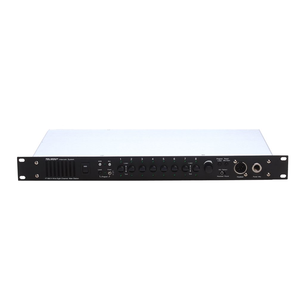
Telikou FT-800 4-wire eight channel main station
I. Introduction
Thank you for choosing TELIKOU intercom products. FT-800 is a 4-wire eight channel main station. ( Four Channel boards are included default.)FT-800 not only can be connected to camera CCU, but also can be connected to BK-104 belt pack which supports Tally function. The FT-800 is suitable for television stations, communications centers, OB trucks, live performance venues and even sports facilities.
The FT-800 utilizes a wired system for stable and reliable performance. Flexible configurations, easy operation, full-duplex communication, clear and loud communication and strong noise resistance are just a few of the advantages of the FT-800.
II. Characteristics
- Announcement output
- Controllable background input
- Automatic circuit short protection and indication.
- Feedback noise suppression
- Eight channels support Tally
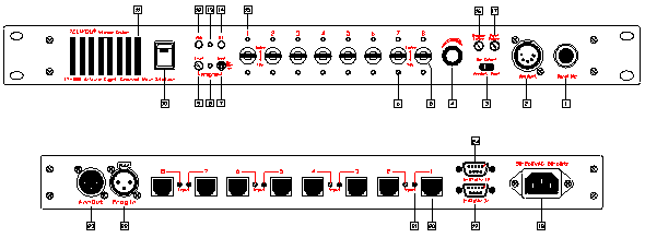
1. Panel Mic Connector
6.35mm (1/4”) unbalanced microphone jack. The microphone type can be dynamic or electric.
6.35mm panel microphone wiring:
T --- Mic Hot
R --- Common
S --- Shield

2. Headset connector
The headset connector is available with either XLR-4M or XLR-5F.
Headset specifications:
EARPHONE: Dynamic 50-2000 ohm
MICROPHONE: Dynamic 200 ohm
Headset wiring:
Pin 1 --- COMMON
Pin 2 --- Mic. HOT
Pin 3 --- Earphone -
Pin 4 --- Earphone +
Pin 5 --- Null
3. Microphone Select Switch
Microphone select switch is used to select between panel microphone or headset microphone.
4. Volume Control
Use this control to adjust the audio level from the FT-800 headset or panel speaker.
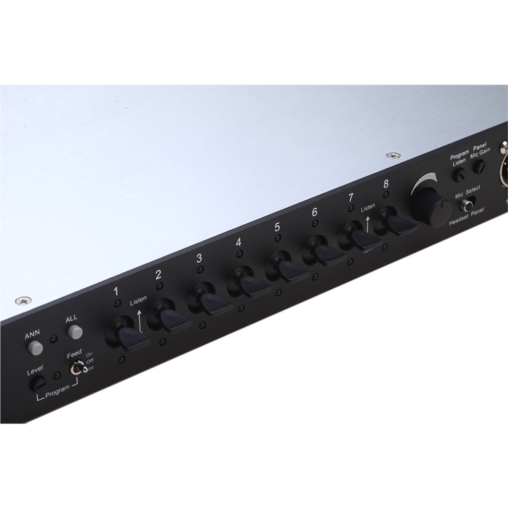
- Channel Button
Lift button enter the monitoring status. The up LED lights.
Press button enter the full duplex communication status. The up and bottom LED lights both light.
1. Long Time Hold: switch is connected. When release the button, switch is cut off.
2. Short time press: if button is lift or pressed quickly, this switch is connected and self-locking. Press again, switch is turned off.
- Talking Light
Green light when talking.
- Program Feed
Turn the switch on or off will send the external signal into intercom channels.
ON: Active channels will receive external program signal and the LED will illuminate.
OFF: External program signal is muted and LED is off.
INT: All the channels receive external program signal. Program signal will be muted when talk switch is turned on.
8. Program Feed LED
This LED illuminates when Program Feed to switch handle is placed at ‘On’ and ‘Int’.
9. Program Level Control
Adjust program audio level which sent to intercom channels.
10. Power Switch and Power LED
Red LED will light when power supply switch is on.
11. Panel Speaker
Panel speaker on when panel microphone is selected.
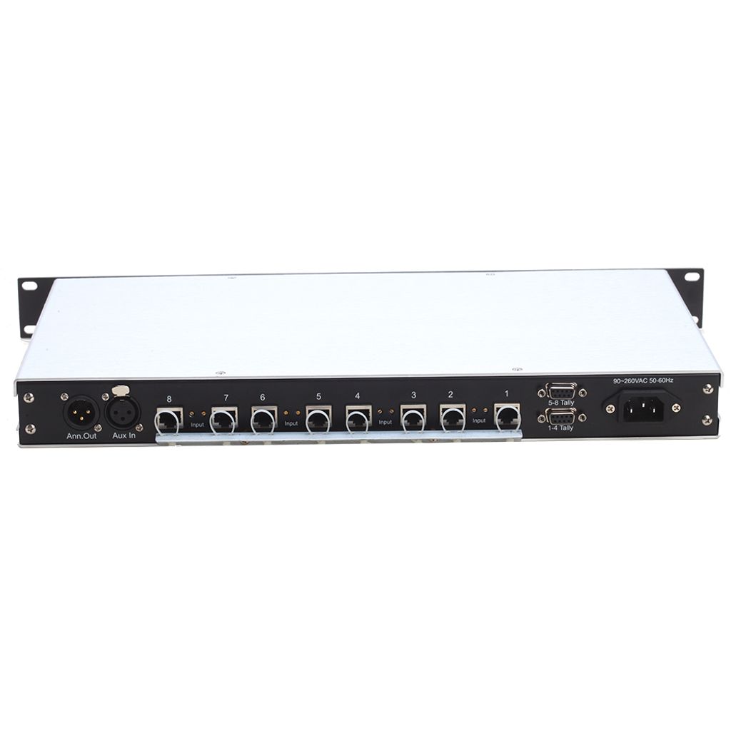
12. ANN
Send the activated microphone signal to ANN. Out connector on the rear panel.
13. ANN LED
When ANN button is pressed, this light on.
14. ALL
When ALL button is pressed, microphone audio is sent to all the channels.
15. Listen LED
When channel switch is lift or pressed, this light on.
16. Program Listen Volume Control
Adjust program audio level which for the FT-800 panel speaker or headset.
17. Panel Mic Gain
Mic gain is used to adjust the panel microphone gain. It has preset for electret microphones
18. AC Power Input
Input Voltage : 90V-260V, Power : Less than 35VA
19. Tally In for 1 - 4 Channel
DB9F pin definition:
Pin 1 --- Green Tally signal to channel 1
Pin 2 --- Red Tally signal to channel 1
Pin 3 --- Green Tally signal to channel 2
Pin 4 --- Red Tally signal to channel 2
Pin 5 --- Green Tally signal to channel 3
Pin 6 --- Red Tally signal to channel 3
Pin 7 --- Green Tally signal to channel 4
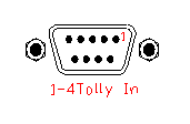
Pin 8 --- Red Tally signal to channel 4
Pin 9 --- Common
Note: low level is efficient.
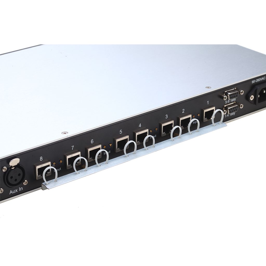
20. 4-Wire Channel Connector
RJ-45 connector. The pin out of connectors is as follows:
Pin 1 --- Ground;
Pin 2 --- +12V;
Pin 3 --- Audio Input +;
Pin 4 --- Audio Output +;
Pin 5 --- Audio Output -;
Pin 6 --- Audio Input -;
Pin 7 --- Green Tally Signal Drive;
Pin 8 --- Red Tally Signal Drive;
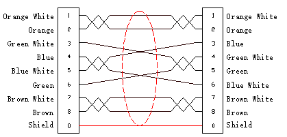
Note: When connect to any other TELIKOU 4-wire device. The RJ-45 connection cable should be made as follow.
21. Channel Input Level Adjustment
Used for balancing external input level to each channel.
22. Program Input
Balanced audio input. Input Level: 1Vp-p.
XLR-3F connector.
Pin 1 --- Common (Shield)
Pin 2 --- Audio Input -
Pin 3 --- Audio Input +
23. Announce Out
Balanced audio output. Output Level: 1Vp-p.
XLR-3M connector.
Pin 1 --- Common (Shield)
Pin 2 --- Audio Output -
Pin 3 --- Audio Output+
24. Tally In for 5 - 8 Channel
DB9F pin definition:
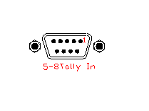
Pin 1 --- Green Tally signal to channel 5
Pin 2 --- Red Tally signal to channel 5
Pin 3 --- Green Tally signal to channel 6
Pin 4 --- Red Tally signal to channel 6
Pin 5 --- Green Tally signal to channel 7
Pin 6 --- Red Tally signal to channel 7
Pin 7 --- Green Tally signal to channel 8
Pin 8 --- Red Tally signal to channel 8
Pin 9 --- Common
Note: low level is efficient.
IV:Connect to CCU
CCU board is optional. Each FT-800 can has max four CCU channel. CCU channel can not talk with any other channel except front panel.
Pin 1 --- Ground;
Pin 2 --- Ground;
Pin 3 --- Audio Input +;
Pin 4 --- Audio Output +;
Pin 5 --- Audio Output -;
Pin 6 --- Audio Input -;
Pin 7 --- Ground;
Pin 8 --- Ground;
CCU channel board adopts transformer coupling. Audio signal can be either differential signal or Non-differential signal.
After connection, FT-800 channel gain may need to be adjusted according to CCU I/O signal.
The step is as follow:
- Turn off all the channels except CCU channel which is need to be adjusted .
- Turn on the camera microphone . Meanwhile, FT-800 headset and camera headset both
can hear each other.
- If the voice heard from FT-800 is not proper. Adjust the Input Level potentionmeter which is beside RJ-45 connector, until the voice level which is heard from FT-800 is proper.
- 4. If the voice heard from camera is not proper. Try the camera voice knob first. If it can not
reach the proper level. Open the top cover.
5. Adjust the Output Level potentionmeter which is at the middle of CCU board, until the
voice which heard from camera headset is proper.
6. Repeat step 1~6 for rest CCU channel.
VI Technical Specification
Audio Bandwidth: 200Hz-4000Hz ±2dB
Earphone impedance: Dynamic 50-2000ohm
Microphone impedance: Dynamic 100-600ohm
4-Wire Channel Input Audio Type: Balanced
4-Wire Channel Output Audio Type: Balanced
4-Wire Channel Input Impedance: >10Kohm
4-Wire Channel Input Level:1Vp-p
4-Wire Channel Output Level: 1Vp-p
POWER SUPPLY:
AC 90-260V, Power : >45VA;
ENVIRONMENTAL:
0° - 70°C(32°-158°F)
Relative Humidity: 0-90%
DIMENSION:
19” (W) x1.75” (H) x9.48” (D), 482mm x 44.5mm x 241mm
WEIGHT:
2.8kG
Note: Please be sure equipment is well connected to the ground for personal safety and devices protection.