
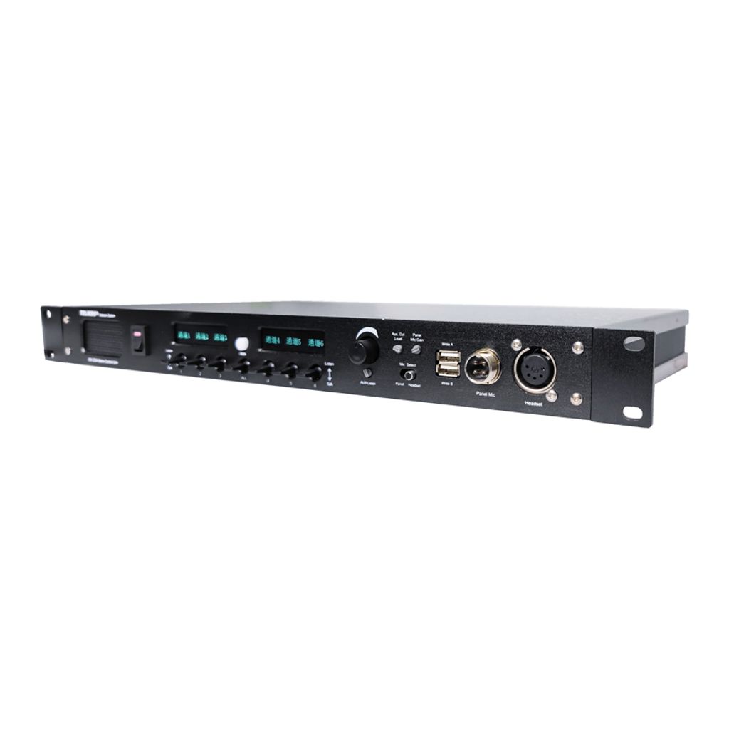
Telikou MX-2304 base station 4-wire six channel Matrix Control Unit
MX-2304 is a special designed six channel 4-wire matrix control unit for small project. With single unit at each point, it can constitute a maximum 7 points full-duplex distributed intercom system. If with extra MX-2304 expanded at each point, the system can be expanded to 13 points. The fault of any MX-2304 will not effect the whole system.
Without the central unit, the MX-2304 system has high cost performance. The disadvantage is the system need more cable connection.
MX-2304 main station is suitable for television station, communication center, UB truck, live performance and any other environment which requires communication. We recommend you read through this manual to better understand the functions of MX-2304.
This system adopts wired connection, and has following features, stable and reliable performance, flexible configuration, full-duplex communication, clear and loud communication sound, easy operation, and strong noise resistance.
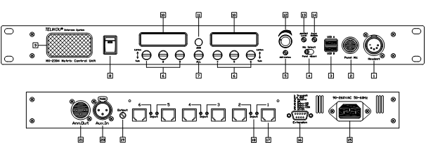
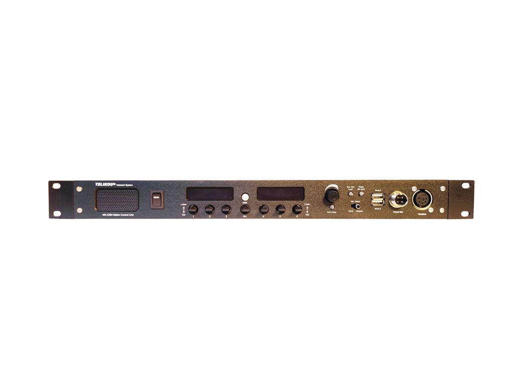
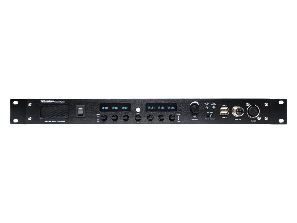
Front Panel
1. Headset connector
4-pin XLR Male or 5-pin XLR Female
EARPHONE: Dynamic 50-2000 ohm
MICROPHONE: Dynamic 200 ohm
The wiring of headset is as follow:
Pin 1 -- Common
Pin 2 -- Mic. hot
Pin 3 -- Earphone -
Pin 4 -- Earphone +
Pin 5 -- Null
2. Panel Mic Connector
6.35mm unbalanced microphone jack. The microphone type can be dynamic or electric.
The definition of 6.35mm plug is as follow:
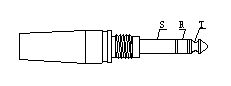
T-- Mic Hot
R-- Common
S-- Shield
3. USB Port (USB A / USB B)
Two USB ports are used to communicate with computer. USB A correspond to Channel 1, 2 and 3. USB B correspond to Channel 4, 5 and 6.
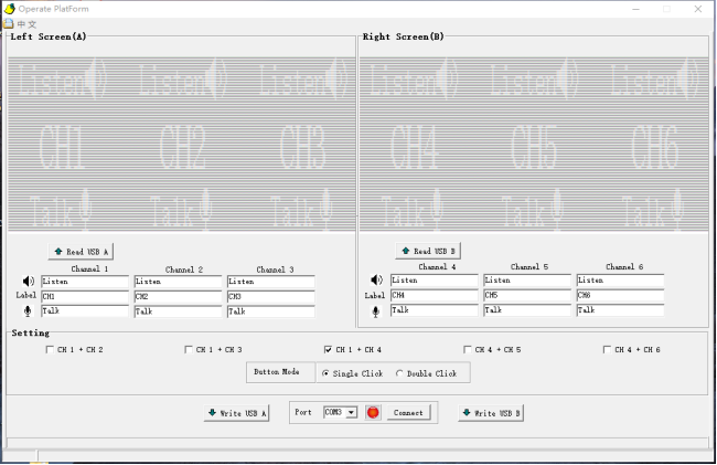
- l LCD Screen Display Area:
Preview Area: Display all the label information.
Input Area:1) Type in Label information through keyboard
- 2) Read label information from MX-2304 through USB port
- l Setting:
Line 1: Select channel group.
This function binds selected channel together. Press any channel button will turn
on the bounded channel together.
Line 2: Button Mode
- 1) Single Click to latch the channel button.
- 2) Double Click to latch the channel button.
Single click the button will release the latched channel.
Hold the channel button is PTT (Push To Talk) mode.
- l COM Select:
Connect MX-2304 and computer through USB cable. Select proper COM port, then click “Connect” . When green LED lights means computer can communicate with MX-2304.
- l Write USB A / USB B:
Write data which displayed on interface into MX-2304,
- 4. Microphone Select Switch
Microphone select switch is used to select panel microphone or headset microphone.
5. Aux In Level Control
Adjust external audio level which input through AUX In connector.
6. Talk & Listen Button
Bi-direction button. Lift button turns on the LISTEN function. Press the button turn on the LISTEN and TALK function. When TALK function is turned on. A CALL is sent to the channel connector at same time.
Button working mode:
PTT -- Hold the button
Latch -- Quick click the button. Press the button again will release the function.
7. ALL
Bi-direction button. Lift button turns on the LISTEN function for all the 6 channels. Press the button turn on the LISTEN and TALK function for all the 6 channels.
8. Power (Power/Power LED)
This red LED will light when power supply switch is on.
- 9. Speaker
Internal 8ohm 3w speaker.
- 10. LCD Screen
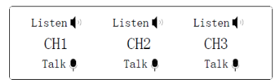
After turn on the power, LCD screen only display channel label. Press channel button will change the channel status and display.
11. ANN. Button
Send the activated microphone signal to ANN. Out connector which is at rear panel.
12. Volume
Adjust the audio level which heard from panel speaker and headset.
13. AUX OUT Level
Adjust the audio level which heard from Intercom channel.
14. Panel Mic Gain
It is used to adjust the panel microphone gain. It has preset with Electret microphone
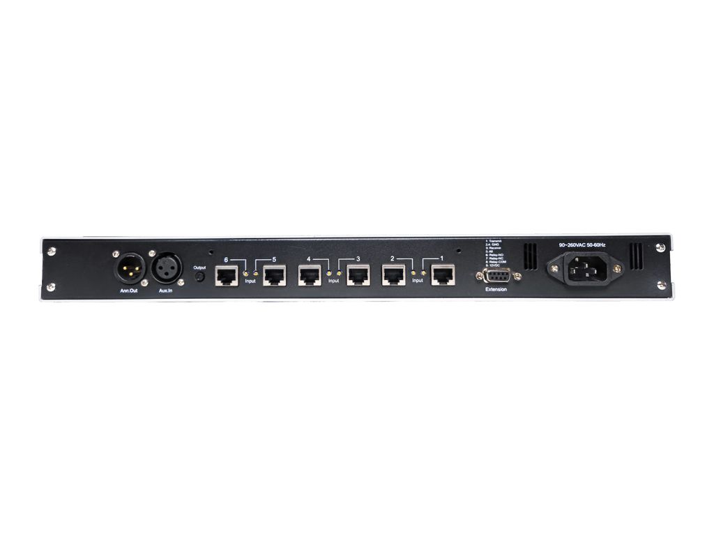
15. Power Connector
AC 90~260V, 50-60Hz
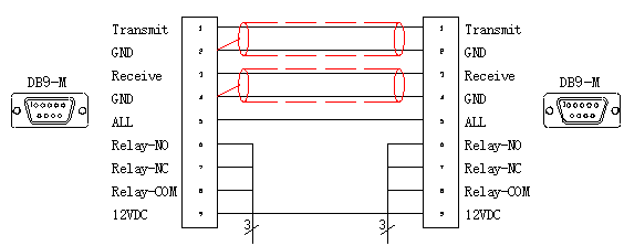
16. Extension Connector (DB9)
If station number is more than 7 in a system. An extension MX-2304 can be connected through this DB9 connector to make a 12 ports point.
The definition of connector is as follow
Pin 1 --- Audio Output
Pin 2 --- Ground
Pin 3 --- Audio Input
Pin 4 --- Ground
Pin 5 --- All Signal
Pin 6 --- Relay No
Pin 7 --- Relay NC
Pin 8 --- Relay Com
Pin 9 --- 12V/1A DC
The extension MX-2304 station can be powered by this DB9 connector.
- 17. Intercom Line connector
RJ-45 connector. The pin out of connectors is as follows:
Pin 1 --- GND
Pin 2 --- Null / +12VDC
Pin 3 --- Audio Input +
Pin 4 --- Audio Output +
Pin 5 --- Audio Output -
Pin 6 --- Audio Input -
Pin 7 --- Control Signal
Pin 8 --- GND
- 18. Input Audio Gain Adjustment
The standard audio level is 1Vp-p. If input audio level is not proper, this knob is used to adjust the audio gain.
- 19. Intercom Channel Output Level Adjustment
The standard audio level is 1Vp-p. This will adjust output level for all six channels.
20. AUX Input
The external audio signal is sent into intercom line through this connector.
Signal Amplitude : 1Vp-p
XLR-3F Pin out is as follow:
Pin 1 --- Ground
Pin 2 --- Audio Input +
Pin 3 --- Audio Input -
21. Announce Out
It sent microphone signal out through this connector.
Signal Amplitude : 1Vp-p
XLR-3M Pin out is as follows:
Pin 1 --- Common (Shield)
Pin 2 --- Audio Output +
Pin 3 --- Audio Output -
IV Technical Specification
Bandwidth: 300Hz-4000Hz ±3dB
Earphone impedance: Dynamic 50-2000ohm
Microphone impedance: Dynamic 100-600ohm
Input Audio Level: 1Vp-p
Output Audio Level: 1Vp-p
Connector Input Impedance: >10Kohm
POWER SUPPLY:
90~240VAC, 50~60Hz;
ENVIRONMENTAL:
0° - 70°C(32°-158°F)
DIMENSION:
19” (W) x1.75” (H) x9.48” (D), 482mm x 44.5mm x 241mm
WEIGHT:
2.8kg